Part-4: Design of RCC beam
The work of the structure designer is to provide the beam size and reinforcement detailing plan to the architect and contractor.
The beam design mainly depends on the total load. it is easy to design a beam, once you understand the basic calculation and design considerations for a reinforced concrete beam.
The question is how to design a beam manually?
Read the complete article and I'm sure you will get the answer.
The basic steps to design a beam is,
- Assume the section size, grade of steel and concrete according to the structure to be built,
- Calculate the total UDL, point load and other loads if applicable,
- Calculate the factored moment,
- Revise the size and grade of materials if required,
- Calculate the area of steel required,
- Provide the reinforcement detail.
The above steps are for simple and singly beam design.
Before going to start the design of beam, let's understand the following three concepts which are useful for design calculation.
Beam type
There are two types of RCC beam, Singly reinforced beam and doubly reinforced beam.
Singly reinforced beam
If the factored moment (`M_{u}`) is less than the limiting moment ( Mulim ) then the beam is designed as a singly reinforced beam.
( Mu<Mulim )
We mostly use the singly reinforced beam in the building if the stresses are less.
The bottom reinforcements are designed to resist the tensile load.
Top reinforcements are also provided in a singly reinforced beam but it is designed to hold the stirrups in position and not designed to be carried the compression load.
Doubly reinforced beam
When the factored moment (Mu) is greater than the limiting moment (Mulim) then the beam is designed as a doubly reinforced beam.
(Mu > Mulim)
The bottom reinforcements are designed to resist the tensile load and top reinforcements are designed to resist the compressive load.
The doubly reinforced beam is most suitable where there is a higher chance of earthquake or stress reversal. also, if an increase in depth is limited for the beam.
Neutral axis
Neatural axis separates the compression and tension zones in the beam. it is denoted by xu. formula to find xu is following,
`x_{u} = \frac{0.87\cdot f_{y} \cdot A_{st}}{0.36 \cdot f_{ck} \cdot b}`
To avoid the brittle failure of concrete, keep the maximum depth of the neutral axis (xumax) always less than the neutral axis (xu).
xu ⊁ xumax
The value of xumax for different grade of steel can be obtained from
IS 456, p- 70 or SP. 16, p-9.
Types of beam section
There are three types of beam section,
Balanced section
In the balanced section,
xu = xumax
pt = ptlim
Mu = Mulim
The strain in concrete and steel will reach their limiting values simultaneously.
Under reinforced section
The steel will fail first with showing the warning if under reinforced section is used in the beam. the failure called ductile failure.
Every designer prefers to design the section according to the under the reinforced section.
xu < xumax
pt < ptlim
Mu < Mulim
Over reinforced section
The concrete will fail first without showing any sign. the sudden failure will occur if the over reinforced section is used. the failure will be called brittle failure.
xu > xumax
pt > ptlim
Mu > Mulim
Load calculation for beam
The loads are transferred from slab to beam. so, we need to calculate that slab load first.
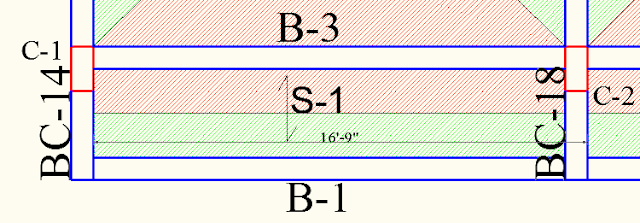
From the above image, it is clear that the slab S-1 is resting on B-1 and B-3 and it is a one-way slab.
To calculate the load on B-1, we need to calculate the load coming from S-1.
I have given the full plan in the previous article you can check it if you directly visited this page.
Slab S-1 is a balcony. the live load for balcony is 3 kN/㎡ and floor finish is taken as 1 kN/㎡. There is no wall resting on B-1.
we assume the slab thickness as 125 mm for this slab. if the slab is bigger, then the 150 mm slab could be assumed it is up to you.
So, the total slab load will be,
Slab load = ( slab thickness x density) + live load + floor finish
= ( 0.125 x 25 ) + 3 + 1
= 7.125 kN/㎡
This is a total load of the slab. the load will transfer in B-1 and B-3. so, the load on B-1 will be,
Imposed load = shorter span X slab load /2
= 1.14 x 7.125/2
= 4.06 kN/m
Self-weight of B-1 = width x depth x density
= 0.230 x 0.450 x 25
= 2.58 kN/m
Wall load = 0
Total load = imposed load + self-weight of beam + wall load
= 4.06 + 2.58 + 0
= 6.64 kN/m
Factored load = Total load x 1.5
= 6.64 x 1.5
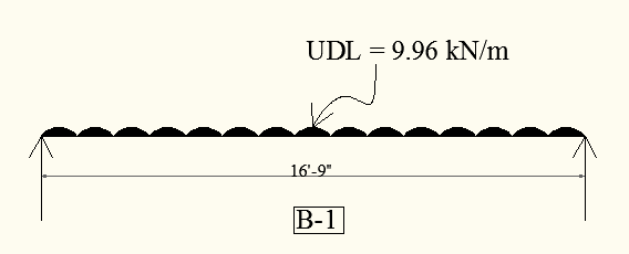
= 9.96 kN/m
The UDL for beam B-1 given in the following image.
Depth of beam
We have assumed the depth D = 450 mm and the breadth B = 230 mm. we mostly change the depth of the beam if the moment is higher.
We have the assumed values are, `f_{ck}` = 20, `f_{y}` = 415, D = 450, B = 230.
Before starting the analysis and design, how we confirm that our assumed depth is sufficient or not. for that, we have a formula which gives approx result let's check that, but first, we need to calculate the factored moment on B-1.
Factored moment = `\frac{wl^2 }{8}`
= `\frac{9.96 X 5.1 X 5.1}{8}`
= 32.38 kN⋅m
Effective depth d = total depth D - cover - Φ
= 450 - 20 - 10
d = 420 mm
Now, we will assume the balanced section which means,
xu = xumax
pt = ptlim
Mu = Mulim
Mulim can be referred to (IS: 456-2000, P. - 96)
`M_{ulim} = 0.36 X \frac{x_{umax}}{d} (1 - 0.42 \frac{x_{umax}}{d}) bd^{2} X f_{ck}`
`32.38 X 10^{6} = 0.36 X 0.479 (1 - 0.42 X 0.479) 230 X d^{2} X 20`
`d^{2} = \frac{32.38 X 10^{6}}{633.64}`
d = 226.05 mm = 230 mm
we can take D = 300 mm which is equal to 12 inches and d will be 270 mm.
We first assumed a 9 x 18-inch beam, from the above calculation it is confirmed that we can reduce the depth of the beam, and now our new beam size is 9 x 12 inches for B-1.
You can calculate the depth for all beams using this formula.
Now, let's do a calculation for the new beam. the slab load will remain the same only self-weight of the beam will be changed.
Imposed load = 4.06 kN/m
Self-weight of beam = width x depth x density
= 0.230 x 0.300 x 25
= 1.73 kN/m
Total load = 4.06 + 1.73
= 5.79 kN/m
Factored load = 5.79 x 1.5
= 8.68 kN/m
Factored moment = `\frac{8.68 X 5.1^{2}}{8}`
Mu = 28.22 kN⋅m
Mulim = 0.138⋅fck⋅b⋅d2 (SP. - 16, P- 10, table - C )
`= 0.138 X 20 X 230 X 270^{2}`
= 46.27 kN⋅m
Mu < Mulim ( ∵ under reinforced section)
Area of steel
After calculating the moment, we can achieve the required area of steel for the particular beam.
There are three different methods for `A_{st}`,
(1) By using design aid method
(2) By using the equation of pt
(3) By using the analytical method
(2) By using the equation of pt
(3) By using the analytical method
We will use the equation of pt to get `A_{st}`,
`p_{t} = 50 \frac{f_{ck}}{f_{y}} [1 - \sqrt{1-\frac{4.6M_{u}}{f_{ck} b d^{2}}} ]`
= 2.40 x 0.22
pt = 0.521 %
`A_{st} = \frac{p_{t}}{100}bd`
`= \frac{0.521}{100} X 230 X 270 `
`A_{st}` = 323.54 mm2
Detailing
When we have the area of steel, we can easily provide the required reinforcement either using IS code or formula.
`a_{st} = \frac{\pi}{4} d^{2}` ( ∵ d = dia. of steel)
For 12 mm, a = 113.04
16 mm, a = 201
20 mm, a = 314
Now, if we use 12 mm dia. steel just simple divide `A_{st}` by 113.04,
Provide, `\frac{323.54}{113.4}`
= 2.85 = 3
Hence,
For B-1, provide 3 nos 12 mm dia. bars.
That's it.
We have got the Final result. we completed the design of the beam. we need to also calculate the other beams.
Let's check the other beam example.
Beam design example
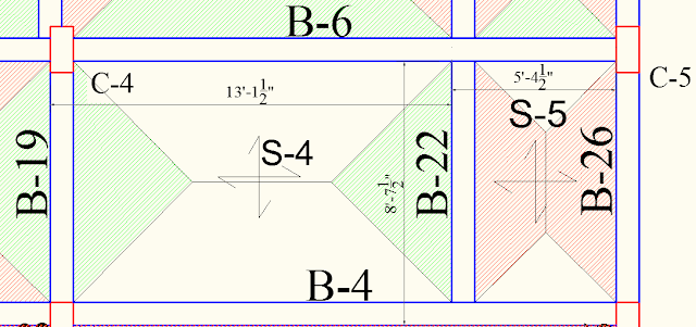
Now, we will calculate the B-22, which transfers both the trapezoidal and triangular load of different slabs.
You can see there is no point load acting on B-22 and it is resting on B-6 and B-4.
The wall of 115 mm thick is resting on B-22.
S-4 is bedroom and S-5 is the toilet. The load for S-4 will be live load = 2 kN/㎡, F.F = 1 kN/㎡ and assumed depth of slab is 125 mm.
S-4 load = (0.125 x 25 + 2+ 1)
= 6.125 kN/㎡
S-5 is a toilet, Sunk load = 4.8 kN/㎡ , and the thickness is 150 mm assumed.
S-5 load = (0.150 x 25 + 4.8)
= 8.55 kN/㎡
let's calculate the imposed load for B-22.
S-4 triangular load = load X shorter span/4
= 6.125 x 2.63/4
= 4.02 kN/m
S-5 trapezoidal load can be given by, `l_{x}` = Shorter span and `l_{y}` = Longer span of slab.
= `\frac{l_{y} + (l_{y} - l_{x})}{2} X \frac{l_{x}}{2} X \frac{load}{l_{y}}`
= `\frac{2.63 + (2.63 - 1.64)}{2} X \frac{1.64}{2} X \frac{8.55}{2.63}`
= 4.82 kN/m
Wall weight = 0.115 x ( 3.04 - 0.450 ) x 20
= 5.96 kN/m
Self-weight of beam = 0.230 x 0.450 x 25
= 2.59 kN/m
Total UDL = 4.02 + 4.82 + 5.96 + 2.59
= 17.39 kN/m
Factored load = 17.39 x 1.5
= 26.08 kN/m
Factored moment Mu = `\frac{26.08 X 2.63^{2}}{8}`
= 22.55 kN⋅m
Assume balanced section,
Mu = Mulim
xu = xumax
`M_{ulim} = 0.36 X \frac{x_{umax}}{d} (1 - 0.42 \frac{x_{umax}}{d}) bd^{2} X f_{ck}`
`22.55 X 10^{6} = 0.36 X 0.479 (1- 0.42 X 0.479) 230 X d^{2} X 20`
d = 188.65 = 200 mm
You can take the beam size of 9 x 9 minimum. but, we will take a 9 x 12-inch size.
Now, let's calculate with a new beam size as 230 mm.
D = 300 mm, d = 270 mm
self-weight of beam = 0.230 x 0.300 x 25
= 1.725 kN/m
Total load = 4.02 + 4.82 + 5.96 + 1.725
= 16.525 kN/m
Factored moment = `\frac{16.525 X 1.5 X 2.63^{2}}{8}`
Mu = 21.43 kN⋅m
Mulim = 0.138⋅fck⋅b⋅d2
`= 0.138 X 20 X 230 X 270^{2}`
= 46.27 kN⋅m
Mu < Mulim ( ∵ under reinforced section)
`p_{t} = 50 \frac{f_{ck}}{f_{y}} [1 - \sqrt{1-\frac{4.6M_{u}}{f_{ck} b d^{2}}} ]`
= 0.384 %
`A_{st} = \frac{p_{t}}{100}bd`
= 239.05 mm
Provide 3 nos 12 mm bars.
We designed the B-22 which is rest in two beams, Which means B-22 is point load for B-4 and B-6.
So, if the load is increased in B-22 will affect the beam B-4 and B-6.
DIY Problem
The design of a beam is based on formulas and calculations. so, you need to practice it more and more to become an expert in the beam design.
I am giving you one example to solve by your self and give the reinforcement detail in the comment section.
Assumed section, 230 x 450 mm, `f_{ck}` = 20 and
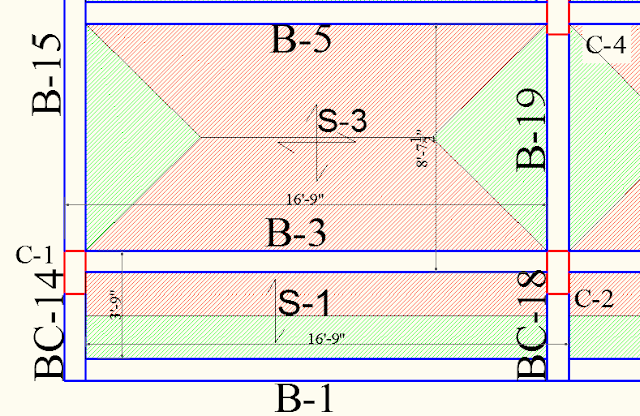
`f_{y}` = 415, d = 420, below S-1 is balcony and S-3 is bedroom,
230 mm thick wall is resting on B-3.height of the floor is
10 feet.
Calculate the Beam B-3 from the below image.
I provided all the necessary information to design the RCC beam for a two-story house. if any point I missed, feel free to tell me in the comment section.
In the next article, we will discuss the cantilever beam design and how to calculate the point load on a beam.


1 comments:
Click here for commentsNice 👍
ConversionConversion EmoticonEmoticon